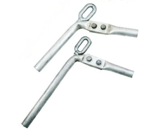
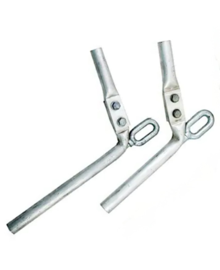
NY Series Strain Clamp For Hydraulic Type
The NY series hydraulic compression clamp is used to attach and connect conductors to the tension insulator cord or fittings on masts and towers by absorbing the tensile force generated by the conductors.
Feature
1. NY compression type tension clamp is composed of aluminum tube and steel anchor. The steel anchor is used to connect and anchor the steel core of the steel core aluminum stranded wire, and then put on the aluminum tube body, using pressure to plastically deform the metal, thereby making the clamp Combined with wires as a whole.
2. Avoid electrical mishaps brought on by icicles adhering to snow, unclean flash, and condensation flash.
3. Prevent the transformer's incoming and outgoing wires from being corroded by acid rain, salt spray, and dangerous chemical fumes.
Model Specification
Model | Suitable
Conductor | Main dimensions (mm) | Grip (kN) |
1 | L] | L2 | L3 | D | D1 | D2 | R |
NY-50/8 | LGJ-50/8 | 355 | 250 | 55 | 190 | 26 | 12 | 16 | 10 | 16.1 |
NY-50/30 | LGJ-50/30 | 405 | 300 | 55 | 190 | 30 | 14 | 16 | 10 | 40.5 |
NY-70/10 | LGJ-70/10 | 385 | 280 | 55 | 200 | 26 | 12 | 16 | 10 | 22.3 |
NY-70/40 | LGJ-70/40 | 455 | 350 | 55 | 200 | 32 | 18 | 16 | 10 | 554 |
NY-95/15 | LGJ-95/15 | 385 | 280 | 55 | 205 | 26 | 14 | 16 | 10 | 33.3 |
NY-95/20 | 1GJ-95/20 | 385 | 280 | 55 | 205 | 26 | 14 | 16 | 10 | 35.4 |
NY-95/55 | LGJ-95/55 | 485 | 380 | 55 | 205 | 34 | 20 | 18 | 11 | 74.2 |
NY-120/7 | 1GJ-120/7 | 385 | 280 | 55 | 205 | 30 | 12 | 16 | 10 | 26.2 |
NY-120/20 | LGJ-120/20 | 405 | 300 | 55 | 205 | 30 | 14 | 16 | 10 | 39.0 |
NY-120/25 | LGJ-120/25 | 425 | 320 | 55 | 205 | 30 | 14 | 16 | 10 | 45.5 |
NY-120/70 | LGJ-120/70 | 535 | 420 | 65 | 215 | 36 | 22 | 18 | 11 | 93.5 |
NY-150/8 | LGJ-150/8 | 400 | 295 | 55 | 210 | 30 | 12 | 16 | 10 | 31.3 |
NY-150/20 | LGJ-150/20 | 425 | 320 | 55 | 210 | 30 | 14 | 16 | 10 | 44.3 |
NY-150/25 | LGJ-150/25 | 435 | 330 | 55 | 210 | 30 | 14 | 16 | 10 | 51.4 |
NY-150/35 | LGJ-150/35 | 455 | 350 | 55 | 210 | 30 | 16 | 16 | 10 | 61.8 |
NY-185/25 | 1GJ-185/25 | 455 | 350 | 55 | 230 | 32 | 14 | 16 | 10 | 56.5 |
NY-185/30 | LGJ-185/30 | 455 | 350 | 55 | 230 | 32 | 16 | 16 | 10 | 61.1 |
NY-185/45 | LGJ-185/45 | 475 | 370 | 55 | 230 | 32 | 18 | 18 | 11 | 76.2 |
NY-240/30 | LGJ-240/30 | 495 | 390 | 55 | 230 | 36 | 16 | 18 | 11 | 71.9 |
NY-240/40 | LGJ-240/40 | 495 | 390 | 55 | 250 | 36 | 16 | 18 | 11 | 79.2 |
NY-240/55 | LGJ-240/55 | 540 | 420 | 65 | 250 | 36 | 20 | 20 | 12 | 97.0 |
NY-300/15 | LGJ-300/15 | 485 | 380 | 55 | 250 | 40 | 14 | 16 | 10 | 64.7 |
NY-300/20 | LGJ-300/20 | 495 | 390 | 55 | 265 | 40 | 14 | 18 | 1 | 71.9 |
NY-300/25 | LGJ-300/25 | 505 | 400 | 55 | 265 | 40 | 14 | 18 | 11 | 79.3 |
NY-300/40 | LGJ-300/40 | 525 | 420 | 55 | 265 | 40 | 16 | 18 | 11 | 876 |
NY-300/50 | LGJ-300/50 | 550 | 430 | 65 | 265 | 40 | 18 | 20 | 12 | 98.3 |
NY-300/70 | LGJ-300/70 | 585 | 460 | 70 | 265 | 42 | 22 | 22 | 13 | 121.6 |
NY-400/20 | LGJ-400/20 | 545 | 440 | 55 | 270 | 45 | 14 | 18 | 1 | 84.4 |
NY-400/25 | LGJ-400/25 | 545 | 440 | 55 | 270 | 45 | 14 | 18 | 11 | 91.2 |
NY-400/35 | LGJ-400/35 | 560 | 440 | 65 | 270 | 45 | 16 | 20 | 12 | 98.7 |
NY-400/50 | LGJ-400/50 | 585 | 460 | 70 | 270 | 45 | 20 | 22 | 13 | 117.3 |
NY-400/65 | LGJ-400/65 | 608 | 480 | 70 | 270 | 48 | 22 | 22 | 13 | 128.5 |
NY-400/95 | LGJ-400/95 | 663 | 520 | 80 | 270 | 48 | 26 | 24 | 15 | 162.8 |
Stable desiqn
Catalog No. | Suitable
Conduclor | Main dimensions (mm) | Grip (kN) |
|
L | L2 | D | DI | D2 | R |
NY-185/30 | JL/G1A-185/30 | 450 | 65 | 32 | 16 | 16 | 10 | 61.3 |
NY-240/30 | JL/GlA-240/30 | 490 | 65 | 36 | 16 | 18 | 11 | 71.4 |
NY-240/40 | JUG1A-240/40 | 490 | 65 | 36 | 16 | 18 | 11 | 79.6 |
NY-300/25 | JL/G1A-300/25 | 505 | 70 | 40 | 14 | 18 | 11 | 79.6 |
NY-300/40 | JL/GIA-300/40 | 525 | 70 | 40 | 16 | 18 | 12 | 88 |
NY-400/35 | JL/GlA-400/35 | 565 | 78 | 45 | 16 | 20 | 13 | 98.5 |
NY-400/50 | JL/G1A-400/50 | 590 | 78 | 45 | 20 | 22 | 13 | 116.9 |
Model | Suitable
Conductor | Main Dimensions (mm) | Grip (kN) |
L | L1 | L2 | L3 | D | D1 | D2 | R |
NY-500/35 | LGJ-500/35 | 590 | 480 | 70 | 260 | 52 | 16 | 22 | 13 | 113.6 |
NY-500/45 | LGJ-500/45 | 590 | 480 | 70 | 260 | 52 | 18 | 22 | 13 | 121.7 |
NY-500/65 | LGJ-500/65 | 620 | 510 | 70 | 260 | 52 | 22 | 22 | 13 | 146.3 |
NY-630/45 | LGJ-630/45 | 610 | 490 | 80 | 290 | 60 | 18 | 22 | 15 | 141.3 |
NY-630/55 | LGJ-630/55 | 635 | 510 | 80 | 290 | 60 | 20 | 24 | 15 | 156.2 |
NY-630/80 | LGJ-630/80 | 675 | 550 | 80 | 290 | 60 | 24 | 24 | 15 | 183.3 |
NY-800/55 | LGJ-800/55 | 725 | 580 | 100 | 335 | 65 | 20 | 26 | 17 | 182.0 |
NY-800/70 | LGJ-800/70 | 775 | 630 | 100 | 335 | 65 | 22 | 26 | 17 | 196.7 |
NY-800/100 | LGJ-800/100 | 775 | 630 | 100 | 335 | 65 | 26 | 26 | 17 | 229.0 |
Stable desiqn
Catalog No. | Suitable
Conductor | Main Dimensions (mm) | Grip (kN) |
L | L2 | D | D1 | D2 | R |
NY-500/45 | JL7G1A-500/45 | 680 | 78 | 52 | 18 | 22 | 13 | 120.9 |
NY-630/45 | JL/G1A-630/45 | 705 | 80 | 60 | 18 | 22 | 15 | 142.9 |
NY-630/55 | JUG1A-630/55 | 715 | 80 | 60 | 20 | 24 | 15 | 156.1 |
Images


The crimping method of hydraulic tension clamps usually includes the following steps
1. Tools and materials that need to be prepared include tension clamps, manual crimping pliers, single-strand bare wires, ring crimp terminals or crimping caps, insulating sleeves, gloves, screwdrivers, etc.
2. Assemble the tension clamp and bare conductor according to the installation requirements.
3. Insert the bare conductor terminal into the tension clamp to ensure complete contact with the bayonet.
4. Add an insulating sleeve to the interface position of the bare wire plug and snap it into the tension clamp.
5. Crimp and tighten. Use your hands or manual crimping pliers to crimp and tighten the tension clamp. Note that the crimping direction of the clamp must be consistent with the compaction direction of the tension clamp.
6. Add a crimping cap or annular crimping terminal to the crimped tension clamp and snap it into the insulating sleeve to ensure a secure connection.
In addition, choosing the correct tension wire clamp is key. Factors such as the model, specifications, tension level, application environment, and required clamping force of the tension wire need to be considered. Before clamping, the tensile wire should be cleaned to remove surface dirt and corrosion, and conductive grease should be applied to the clamping position to ensure conductivity. During the crimping process, a hydraulic press should be used to apply pressure to ensure that the clamp arm is pressed tightly so that the clamping point reaches the required locking force. After the crimping is completed, the clamps and clamping points should be inspected to ensure that the quality meets standard requirements.


